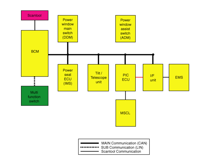
The 6 components related
with Body Control Module(hereinafter referred to BCM) connect with each
other via CAN(Controller Area Network) communication system. These are
BCM. Assist Door Module (ADM), Drive Door Module (DDM), Power Seat Unit
(PS), tilt/telescope control unit and Personal Identification Card
(PIC).
Wiper Motor Module (WMM)
and Mulit-Function Switch (M/F) connect with BCM via LIN (Local
Interconnect Network). Therefore it is possible to diagnose an overall
system with scantool.
*¹ CAN (Cotroller Area
Network) : CAN is a serial bus system especially suited for networking
"intelligent" devices as well as sensors and actuators within a system or
sub-system.
*² LIN (Local
Interconnect Network) : LIN is a new low cost serial communication system
intended to be used for distributed electronic systems in vehicles, which
complements the existing portfolio of automotive multiplex
networks.

This code means that
there is a problem in LIN communcation line between BCM and M/F (multi
function) switch / WMM(wiper motor module). This code is set if BCM
message is not transmitted to M/F switch and MM on time. Possible cause is
short circuited to ground or battery in LIN communcation line. When BCM
receives LIN data, it verifies the data by comparing it with feedback data
which received from LIN IC receiving line.
Item
|
Detecting
Condition
|
Possible cause
|
DTC
Strategy
|
| •
|
Check CAN communition
state. | |
| •
|
LIN communication line short to ground /
battery. |
| •
|
The function for Transmitting data of
the BCM do not operate
normally. | |
Enable
Conditions
|
| •
|
BCM is not transmitted a message to M/F
switch and WMM via CAN
line. | |
Threshold
Value
|
| •
|
LIN communication line short to
ground. |
| •
|
LIN communication line short to
battery. | |
Diagnostic
Time
|
|


| 1. |
Ignition "OFF", connect
scantool. |
| 2. |
Ignition "ON" & Engine "OFF", select
"Diagnostic Trouble Codes(DTC)"
mode. |
| 3. |
Monitor diagnostic trouble code and present of
trouble code. |
| 4. |
Using a scan tool, clear the DTC.

|
| 5. |
Are any DTC present?
|

|
▶ Go to
"W/Harness Inspection" procedure.
|
|

|
▶
Displaying nothing(no DTC) shows that Fault is intermittent
caused by poor contact in the part's and/or WMM AND M/F SW
connector or was repaired and BCM memory was not
cleared.
Thoroughly check
connectors for looseness, poor connection, bending, corrosion,
contamination, deterioration, or damage.
▶ Repair or replace as necessary and then go to
"Verification of Vehicle Repair"
procedure.
|
|
| Terminal And Connector
Inspection |
| 1. |
Many malfunctions in the electrical system are
caused by poor harness(es) and terminals. Faults can also be caused
by interference from other electrical systems and mechanical or
chemical damage. |
| 2. |
Check the following conditions:
| (1) |
Check for damaged harness and terminals:
contact resistance, oxidation, bent or broken
terminals. |
| (2) |
Check for poor connection between ECM
and component: backed out terminal, improper mating, broken
locks and poor terminal to wire
connection. |
|
Using a suitable male pin to ensure that
contact in sockets is good. The pin should remain in position
when pulled
gently. | |
| 3. |
Has a problem been found?
|

|
▶ Repair as
necessary and then go to "Verification of Vehicle Repair"
procedure.
|
|

|
▶ Go to
"WMM AND M/F SW Signal Circuit Inspection"
procedure.
|
|
| WMM And M/F SW Control Unit Signal Circuit
Inspection |
| 1. |
Check LIN communication circuit
| (1) |
Ignition "ON" and Engine
"OFF" |
| (2) |
Connect scantool and select VEHICLE
SCOPEMETER function. |
| (3) |
Measure waveform between "LIN
communication" of WMM AND M/F SW connector and chassis
ground.
Specification : If
LIN communication waveform is displayed, it is
OK.
| |
| (4) |
Is LIN communication waveform displayed
within specification?
|

|
▶
Thoroughly check connectors for looseness, poor
connection, bending, corrosion, contamination,
deterioration or damage.
Repair or replace as necessary and then go to
"Verification of Vehicle Repair"
procedure.
|
|

|
▶
Check the the LIN communication harness of the WMM AND
M/F SW for an open and short.
Repair as necessary and then go to
"Verification of Vehicle Repair"
procedure.
|
| |
| Verification Of Vehicle
Repair |
After a repair, it is
essential to verifying that the fault has been corrected.
| 1. |
Connect scan tool and select "Diagnostic
Trouble Codes(DTCs)" mode. |
| 2. |
Using scantool, Clear
DTC. |
| 3. |
Operate the vehicle within DTC Enable
conditions in General information. |
| 4. |
Are any DTCs present ?
|

|
▶ Go to the
applicable troubleshooting procedure.
|
|

|
▶ System is
performing to specification at this
time.
|
|