When the engine is first
started, the fuel control system operates in an open loop operation,
ignoring the HO2S(Heated Oxygen Sensor) signal and calculating the
air/fuel ratio based on inputs from the engine coolant temperature, the
throttle position and the mass air flow sensors. The PCM will begin by
using the oxygen sensor signal for controlling the fuel delivery(closed
loop) when the following conditions are met:
| - |
The engine has run a minimum amount of time at
engine start up. |
| - |
The HO2S has a varying voltage output showing
that it is hot enough to operate
properly. |
| - |
The ECT has increased a minimum amount based
on the ECT at start up. |
The PCM monitors the
amount of time for the cooling system to achieve closed loop operating
temperature. The engine coolant temperature sufficient to allow closed
loop operation is not achieved within a predetermined time frame, PCM sets
DTC.
Checking time and
coolant temperature under detecting condition, if the engine coolant
temperature dose not exceed the coolant temperature threshold before the
determinated period elapses, PCM sets P0125. MIL(Malfunction Indication
Lamp) turns on when the malfunction lasts till consecutive 2 driving
cycle.
Item
|
Detecting
Condition
|
Possible Cause
|
DTC
Strategy
|
| •
|
Monitor the engine coolant temperature
and time | |
|
Enable
condition
|
| •
|
Coolant sensor is
normal |
| •
|
Startup coolant temp ≤ 10°C( 50
°F) |
| •
|
No disabling faults(DTCs related to
MAFS/MAPS, catalyst, fuel system or engine oil temperature
sensor) | |
threshold
value
|
| •
|
The engine coolant temperature dosen't
reach the coolant temperature threshold within predeterminated
period | |
diagnosis
time
|
|
MIL ON
condition
|
|
Temp. (°C/°F)
|
Resistance (kΩ)
|
Temp. (°C/°F)
|
Resistance
(kΩ)
|
-40(-40)
|
48.14
|
40(104)
|
1.15
|
-20(-4)
|
14.13 ~
16.83
|
60(140)
|
0.59
|
0(32)
|
5.79
|
80(176)
|
0.32
|
20(68)
|
2.31 ~
2.59
|
|
|

| 1. |
Check DTC Status
| (1) |
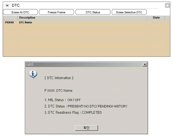
Connect scantool to Data Link
Connector(DLC). |
| (3) |
Select "DTC" button, and then Press "DTC
Status" to check DTC's information from the DTCs
menu. |
| (4) |
Read "DTC Status"
parameter.

|
| (5) |
Is parameter displayed "Present
fault"?
|

|
▶ Go
to "Component inspection" procedure.
|
|

|
▶
Fault is intermittent, go to "Verification of Vehicle
Repair"
procedure.
|
| |
| 1. |
IG "OFF" and disconnect ECTS
connector. |
| 3. |
Measure resistance between signal and ground
terminals of ECTS connector as the temperature rises.
Specificaton :
Temp.
(°C/°F)
|
Resistance
(kΩ)
|
-40(-40)
|
48.14
|
-20(-4)
|
14.13
~ 16.83
|
0(32)
|
5.79
|
20(68)
|
2.31 ~
2.59
|
40(104)
|
1.15
|
60(140)
|
0.59
|
80(176)
|
0.32
|
|
| 4. |
Are the measured resistance within
specification?
|

|
▶ Clear DTC
and Test-drive under enable conditions above-mentioned. After
the test, If this DTC is set, recheck it thoroughly. If not,
it is intermittent fault, go to Verification of vehicle
Repair" procedure.
|
|

|
▶
Substitute with a known - good ECTS and check for proper
operation.
▶ If the problem is
corrected, Go to "Verification of Vehicle
Repair"procedure.
|
|
| Verification Of Vehicle
Repair |
After a repair, it is
essential to verify that the fault has been corrected.
| 1. |
Connect scantool and select "DTC"
button. |
| 2. |
Press "DTC Status" button and confirm that
"DTC Readiness Flag" indicates "Completed". If not, drive the
vehicle within conditions noted in the freeze frame data or enable
conditions |
| 3. |
Read "DTC Status"
parameter |
| 4. |
Is parameter displayed "History(Not Present)
fault"?
|

|
▶ System
performing to specification at this time. Clear the
DTC
|
|

|
▶ Go to the
applicable troubleshooting
procedure.
|
|