
The CVVT (Continuously
Variable Valve Timing) system is installed to the chain sprocket of the
intake camshaft. This system controls the intake camshaft to provide the
optimal valve timing. The PCM controls the Oil Control Valve(OCV), based
on the signals output from mass air flow, throttle position and engine
coolant temperature. The CVVT controller regulates the intake camshaft
angle using oil pressure through the OCV. As result, the relative position
between the camshaft and the crankshaft becomes optimal, and the engine
torque improves, fuel economy improves, exhaust emissions decrease under
overall driving conditions.
When the enable
condition is satisfied, The PCM checks that OCV outputs (Voltage level)
are observed when OCVs are commanded. When a OCV output failure is
detected, the appropriate fail counter is incremented.
If the failure threshold
is exceeded 5 seconds during one diagnostic test(10second), the test is
failed and DTC is stored. MIL(Malfunction Indication Lamp) turns on when
the malfunction lasts till consecutive 2 driving cycle.
Item
|
Detecting
Condition
|
Possible cause
|
DTC
Strategy
|
| •
|
Detects a short to
battery | |
| •
|
Short to battery in Control
Circuit |
|
Enable
Conditions
|
| •
|
No disabling Faults
Present |
| •
|
11V ≤ Ignition Voltage ≤
16V | |
Threshold
value
|
|
Diagnosis
Time
|
| •
|
Continuous
(More than 5 seconds failure for every
10 seconds test ) | |
MIL On
Condition
|
|
Resistance
(Ω)
|
6.7 ~ 7.7 Ω
at 20 °C (68 °F)
|


The oil control valve is
commanded by a pulse-width-modulated signal from the engine control unit.
A duty cycle of zero commands the cam phaser to its default position. A
duty cycle of 100% commands the phaser to its maximum phased position.
When the phaser must be controlled to an intermediate position, the duty
cycle is maintained in the region of the ‘hold position'. This is a medium
duty cycle, usually between 35% and 65%, depending on temperature and
voltage conditions.
| 1. |
Check DTC Status
| (1) |
Connect scantool to Data Link
Connector(DLC). |
| (3) |
Select "DTC" button, and then Press "DTC
Status" to check DTC's information from the DTCs
menu. |
| (4) |
Read "DTC Status"
parameter.

|
| (5) |
Is parameter displayed "Present
fault"?
|

|
▶ Go
to "Terminal and connector inspection"
procedure.
|
|

|
▶
Fault is intermittent caused by poor contact in the
sensor's and/or PCM's connector or was repaired and PCM
memory was not cleared. Thoroughly check connectors for
looseness, poor connection, ending, corrosion,
contamination, deterioration, or damage. Repair or
replace as necessary and go to "Verification of Vehicle
Repair"
procedure.
|
| |
| Terminal And Connector
Inspection |
| 1. |
Many malfunctions in the electrical system are
caused by poor harness and terminal condition. Faults can also be
caused by interference from other electrical systems, and mechanical
or chemical damage. |
| 2. |
Thoroughly check connectors for looseness,
poor connection, bending, corrosion, contamination, deterioration,
or damage. |
| 3. |
Has a problem been found?
|
|
▶ Repair as
necessary and go to "Verification of Vehicle Repair"
procedure
|
|
|
▶ Go to "
Control Circuit Inspection "
procedure.
|
|
| Control Circuit
Inspection |
■ Check Short To Battery In Harness
| 1. |
IG "OFF" and Disconnect OCV
connector. |
| 2. |
Measure resistance between power and control
terminals of OCV harness connector.
|
| 3. |
Is the measured resistance within
specification ?
|
|
▶ Go to
"Component Inspection" procedure.
|
|
|
▶ Repair or
replace as necessary and go to "Verification of Vehicle
Repair"
procedure.
|
|
■ Check OCV Resistance
| 1. |
IG "OFF" and disconnect OCV
connector. |
| 2. |
Measure resistance between power and signal
terminals of OCV. (Component Side)
Specification
: 6.7 ~ 7.7 Ω
| |
| 3. |
Is the measured resistance within
specification ?
|
|
▶ Go to
"OCV Actuation Test" as follows.
|
|
|
▶
Substitute with a known - good OCV and check for proper
operation. If the problem is corrected, replace OCV and go to
"Verification of Vehicle Repair"
procedure.
|
|
■ OCV Actuation Test
| 1. |
Connect scantool and IG
"ON". |
| 2. |
Select "OCV" on the Actuation
Test. |
| 3. |
Activate "OCV" by pressing "STRT(F1)"
key.
(should hear a faint click from Oil Control
solenoid Valve) |
| 4. |
Repeat this procedure 4 or 5 times to ensure
intake valve control solenoid reliability.
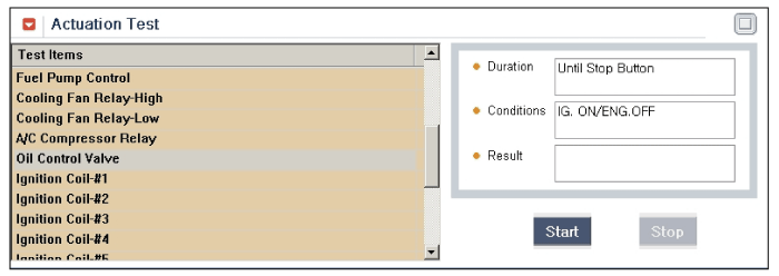
|
| 5. |
Does OCV generate click sound during acutation
test ?
|
|
▶
Substitute with a known - good PCM and check for proper
operation. If the problem is corrected, replace PCM and go to
"Verification of Vehicle Repair" procedure.
|
There is a memory reset function
on scantool that can erase optional parts automatically
detected and memorized by PCM.Before or after testing
PCM on the vehicle, use this function to reuse the PCM
on the others | |
|
|
▶
Substitute with a known - good OCV and check for proper
operation. If the problem is corrected, replace OCV and go to
"Verification of Vehicle Repair"
procedure.
|
|
| Verification Of Vehicle
Repair |
After a repair, it is
essential to verify that the fault has been corrected.
| 1. |
Connect scantool and select "DTC"
button. |
| 2. |
Press "DTC Status" button and confirm that
"DTC Readiness Flag" indicates "Completed". If not, drive the
vehicle within conditions noted in the freeze frame data or enable
conditions |
| 3. |
Read "DTC Status"
parameter |
| 4. |
Is parameter displayed "History(Not Present)
fault"?
|
|
▶ System
performing to specification at this time. Clear the
DTC
|
|
|
▶ Go to the
applicable troubleshooting
procedure.
|
|