The PCM provides a 5volt
reference voltage to Throttle Position Sensor 2(TPS2). The PCM monitors
reference voltage deviation from the power supply circuit of the
sensors.
Checking the voltage
from sensor power supply every 1.87 sec. under detecting condition, if the
value within detecting condition lasts for more than 0.2 sec., PCM sets
P0651. MIL(Malfunction Indication Lamp) turns on when the malfunction
lasts till consecutive 2 driving cycle.
Item
|
Detecting
Condition
|
Possible Cause
|
DTC
Strategy
|
| •
|
Sensor reference voltage
check | |
| •
|
Short in sensor power supply
line |
|
Enable
condition
|
|
threshold
value
|
| •
|
Sensor supply power < 4.5V or >
5.5V | |
diagnosis
time
|
| •
|
Continuous
(More than 0.2 seconds failure for every
1.87 seconds test ) | |
MIL ON
condition
|
|
| 1. |
Check DTC Status
| (1) |
Connect scantool to Data Link
Connector(DLC). |
| (3) |
Select "DTC" button, and then Press "DTC
Status" to check DTC's information from the DTCs
menu. |
| (4) |
Read "DTC Status"
parameter.

|
| (5) |
Is parameter displayed "Present
fault"?
|

|
▶ Go
to "Terminal and connector inspection"
procedure.
|
|

|
▶
Fault is intermittent caused by poor contact in the
sensor's and/or PCM's connector or was repaired and PCM
memory was not cleared. Thoroughly check connectors for
looseness, poor connection, ending, corrosion,
contamination, deterioration, or damage. Repair or
replace as necessary and go to "Verification of Vehicle
Repair"
procedure.
|
| |
| Terminal And Connector
Inspection |
| 1. |
Many malfunctions in the electrical system are
caused by poor harness and terminal condition. Faults can also be
caused by interference from other electrical systems, and mechanical
or chemical damage. |
| 2. |
Thoroughly check connectors for looseness,
poor connection, bending, corrosion, contamination, deterioration,
or damage. |
| 3. |
Has a problem been found?
|
|
▶ Repair as
necessary and go to "Verification of Vehicle Repair"
procedure
|
|
|
▶ Go to
"Power Circuit Inspection"
procedure.
|
|
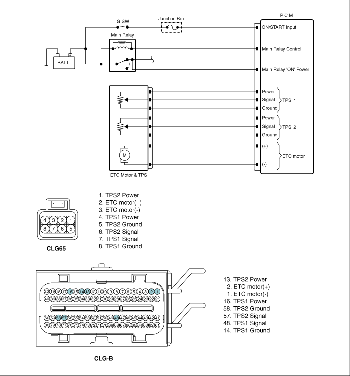
■ Check voltage
| 1. |
IG "OFF" and disconnect ETC Motor & TPS
connector. |
| 3. |
Measure voltage between TPS2 power terminal of
ETC Motor & TPS harness connector and chassis
ground.
Specification
: Approx. 5V
| |
| 4. |
Is the measured voltage within specification
?
|
|
▶
Thoroughly check connectors for looseness, poor connection,
bending, corrosion, contamination, deterioration, or damage.
Repair as necessary and go to "Verification of Vehicle Repair"
procedure.
|
|
|
▶ Go to
"Check short in harness" as
follows.
|
|
■ Check short in power harness
| 2. |
Disconnect ETC Motor & TPS connector and
PCM connector. |
| 3. |
Measure the resistance between TPS2 power and
ETC motor (+) terminals of ETC Motor & TPS harness
connector.(Measurement "A") |
| 4. |
Measure the resistance between TPS2 power and
ETC motor (-) terminals of ETC Motor & TPS harness
connector.(Measurement "A") |
| 5. |
Measure the resistance between TPS2 power and
TPS1 ground terminals of ETC Motor & TPS harness
connector.(Measurement "B") |
| 6. |
Measure the resistance between TPS2 power and
TPS2 ground terminals of ETC Motor & TPS harness
connector.(Measurement "B")
|
| 7. |
Is the measured resistance within
specification ?
|
|
▶
Substitute with a known - good PCM and check for proper
operation. If the problem is corrected, replace PCM and go to
"Verification of Vehicle Repair" procedure.
|
|
|
▶ Repair
Short in power harness and go to "Verification of Vehicle
Repair" procedure.
|
※ Procedure of ETS Initialization
1. Erase the trouble codes on PCM
2. Turn the ignition key off and keep this
condition until the main relay is turned off.(It will take 10
seconds)
3. Turn ignition key on more than 1second to
record the throttle motor position on the
EEPROM |
| Verification Of Vehicle
Repair |
After a repair, it is
essential to verify that the fault has been corrected.
| 1. |
Connect scantool and select "DTC"
button. |
| 2. |
Press "DTC Status" button and confirm that
"DTC Readiness Flag" indicates "Completed". If not, drive the
vehicle within conditions noted in the freeze frame data or enable
conditions |
| 3. |
Read "DTC Status"
parameter |
| 4. |
Is parameter displayed "History(Not Present)
fault"?
|
|
▶ System
performing to specification at this time. Clear the
DTC
|
|
|
▶ Go to the
applicable troubleshooting
procedure.
|
|