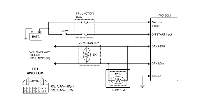
CAN communication is a
parallel circuit to interchange information among each units.
CAN communication can
share much information with units more faster and more efficiently by
using specified language.
CAN-High line is twisted
with CAN-Low line as a purpose in preventing from a noise.
The operating duty of
EMC is maintained at 100 : 0 (2WD) for guaranteeing stabilized driving
force, accuracy of the control during inside ABS, FTCS, ESP
control.

This code related to
communication line between HECU(ESP) and "4WD-ECM" is set when CAN signal
from HECU(ESP) can't received for more than 1sec or ECU internal error
occur.
If failure is detected
"4WD-ECM" prohibits the "ITCC" control and cuts the current to control
coil.
Item
|
Detecting
Condition
|
Possible Cause
|
DTC
Strategy
|
| •
|
Wheel Speed Signal
error | |
| •
|
Connector looseness and poor terminal to
wire connection. |
| •
|
CAN HIGH/LOW circuit
open/short. |
| •
|
Faulty CAN
MODULE.(ESP) |
|
Threshold
Value
|
| •
|
Condition1: Wheel speed signal value is
invalid (over 511.875km/h), and maintained over 0.5 sec.(over
99.603%), and maintained over 0.5 sec.
Conditon2: Data can’t be received in 0.5
sec.
Condition3: No receiving of data for 0.5
sec after ignition is turned
ON. | |
Fail
Safe
|
|


| 1. |
Connect scantool to Data Link
Connector(DLC). |
| 2. |
Warm up the engine to normal operating
temperature. |
| 3. |
Monitor DTC(Diagnostics Trouble Code) on the
scantool.

|
| 4. |
Is the same DTC displayed again?
|

|
▶ Go to "
Inspection/Repair " procedure .
|
|

|
▶ Fault is
intermittent caused by poor contact in the sensor’s and/or
"4WD-ECM"s connector or was repaired and "4WD-ECM" memory was
not cleared.
Thoroughly check
connectors for looseness, poor connection, bending, corrosion,
contamination, deterioration, or damage.
Repair or replace as necessary and go to
"Verification of vehicle Repair"
procedure
|
|
| Terminal And Connector
Inspection |
| 1. |
Many malfunctions in the electrical system are
caused by poor harness and terminals.
Faults can also be caused by interference from
other electrical systems, and mechanical or chemical
damage. |
| 2. |
Thoroughly check connectors for looseness,
poor connection, bending, corrosion, contamination, deterioration,or
damage. |
| 3. |
Has a problem been found?
|

|
▶ Repair as
necessary and go to "Verification of Vehicle Repair"
procedure.
|
|

|
▶ Go to
"Signal circuit Inspection-CAN"
procedure.
|
|
| Signal Circuit
Inspection |
Signal Circuit Inspection-CAN
| 2. |
4WD ECM, EMC connector :
Connect. |
| 3. |
IG KEY : ON, Engine :
ON. |
| 4. |
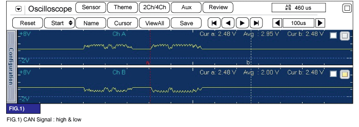
Monitor signal waveform between CAN(HIGH, LOW)
of "4WD-ECM" harness connector and chassis
ground. |
| 5. |
Start and drive vehicle in gear and maintain
vehicle speed is approx. 10km/h or less(6mph or less)
Specification
: Signal Waveform &
Data
|
|
The above value is only for
reference.
The actual value may differ from it
according to various engine
condition. | |
| 6. |
Is "Signal display" near the specified
value?
|

|
▶ Fault is
intermittent caused by poor contact in the sensor’s and/or
"4WD-ECM"s connector or was repaired and "4WD-ECM" memory was
not cleared.
Thoroughly check
connectors for looseness, poor connection, bending, corrosion,
contamination, deterioration, or damage.
Repair or replace as necessary and go to
"Verification of vehicle Repair" procedure.
|
|

|
▶ Go to
"CAN comm. Line Inspection(Open/Short) "
procedure.
|
|
| Control Circuit
Inspection |
CAN Comm, Line Inspection(Open/Short)
| 3. |
Measure resistance between CAN(HIGH) terminal
of 4WD ECM harness connector and CAN(LOW) terminal of 4WD ECM
harness connector.
Specification
: Approx. 60Ω
|
|
The above value is only for
reference.
The actual value may differ from it
according to various engine
condition. | |
| 4. |
Is "resistance" display near the specified
value?
|

|
▶ Fault is
intermittent caused by open or short in CAN signal harnessor
was repaired and "4WD-ECM" memory was not
cleared.
Go to the applicable
troubleshooting procedure.
|
|

|
▶ Check for
open or short in TCCU communication circuit.
▶ Check HECU(ESP) or their signal.
▶ Repair or replace as necessary and go to
"Verification of vehicle Repair"
procedure.
|
|
| Verification of Vehicle
Repair |
After a repair, it is
essential to verify that the fault has been corrected.
| 1. |
Connect scan tool and select "Diagnostic
Trouble Codes(DTCs)" mode |
| 2. |
Using a scantool, Clear
DTC. |
| 3. |
Operate the vehicle within DTC Enable
conditions in General information. |
| 4. |
Are you DTCs present?
|

|
▶ Go to the
applicable troubleshooting procedure.
|
|

|
▶ System
performing to specification at this
time.
|
|